 Torsional system
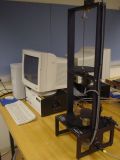
The ECP torsional system (Model 205) consists of 1 till 3 rotational inertia connected by flexible shafts. The position of each inertia can be measured by an optical encoder in real-time, whereas the bottom inertia can be actuated by a torgue from a brushless DC motor. The system represents the dynamics found in many mechanical systems including rigid bodies; flexibility in drive shafts, gearing and belts; and coupled discrete vibration with actuator at the drive input and sensor collocated or at flexibly coupled output (non-collocated). The experiment can be set up such that the dynamical behavior ranges from a simple double integrator (rigid body motion) to a 6th order dynamical system with lightly damped poles. A more detailed description of the torsional system experiment can be found in the ECP manual in the download section. Also check out the movies of the (un)controlled torsional system in the download section.
 Industrial emulator
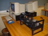
The ECP industrial emulator system (Model 220) consists of several disks connected by flexible belts. By moving the location of brass weights attached to the discs, the effective inertia of the disks can be changed. The position of the disks can be measured by optical encoders in real-time. One of the disks is attached to a brush less DC-motor and disturbances can be generated for the system to emulate non-linear phenomena often encountered in industrial applications. Disturbances and non-ideal properties that can be introduced and removed from the system include backlash, drive friction, and force disturbances. The disturbances can be applied in a controlled manner to facilitate the study of control approaches to mitigate their effects. A more detailed description of the industrial emulator experiment can be found in the ECP manual in the download section.
 Rectilinear system
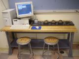
The ECP rectilinear system (Model 210) consists of 1 till 3 carts connected by flexible springs. The mass of each cart can be changed by brass weights and the position can be measured by an optical encoder in real-time. The first (left) cart can be actuated by a horizontal force from a brush less DC motor and gearbox. The last (utmost right) cart can be connected to a damper to emulate a damped mechanical system. The system represents the dynamics found in many mechanical systems including rigid bodies; flexibility in drive shafts, gearing and belts; and coupled discrete vibration with actuator at the drive input and sensor collocated or at flexibly coupled output (non-collocated). The experiment can be set up such that the dynamical behavior ranges from a simple double integrator (rigid body motion) to a 6th order dynamical system with lightly damped poles. A more detailed description of the rectilinear system experiment can be found in the ECP manual in the download section. Also check out the movies of the rectilinear system in the download section.
 Moment gyroscope system
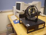
The ECP moment gyroscope system (Model 750) consists of a high inertia brass rotor suspended in an assembly with four angular degrees of freedom. Torque is applied via direct-acting, reaction, or gyroscopic drive mechanizations. One or two such input torques may be applied simultaneously and the degrees of freedom may be constrained in such a way as to create plants ranging from simple one degree of freedom rigid bodies to complex systems with two torque inputs and four angular outputs. The rotor spin torque is provided by a rare earth magnet type DC motor, whose angular position is measured by an optical encoder. The first transverse gimbal assembly is driven by another rare earth motor to effect motion about its axis, generating a gyroscoping torque for angular motion of the second gimbal assembly. Additional encoders can be used to measure the angular position of each gimbal assembly. The system may be operated in regions where its predominant behavior is linear, or in a more global workspace where the behavior is highly nonlinear due to singular points. This dynamically rich system provides a testbed for experiments ranging from demonstration of fundamental principles to advanced research. A more detailed description of the gyroscope system experiment can be found in the ECP manual in the download section.
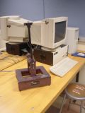 Inverted pendulum system
The ECP inverted pendulum system (Model 505) consists of a unique mechanism that provides vivid demonstrations and challenging experiments for both undergraduate and graduate studies in controls. Unlike conventional pendulum systems mounted on a cart or a rotary actuator, this pendulum system steers a horizontal sliding rod in the presence of gravity to balance and control the position of the vertical rod (pendulum). The mechanism is inherently open loop unstable (right half plane pole) and non-minimum phase (right half plane zero). The location of the unstable poles and zeros of the system can be modified, by moving brass weights mounted on the horizontal and vertical rod. The experiment design and the control design problem is challenging due to the instability of the system. Furthermore, the structure of the feedback controller must be selected carefully due the non-minimum phase characteristics of the system. A more detailed description of the inverted pendulum system can be found in the ECP manual in the download section. Also check out the movies of the inverted pendulum system in the download section.
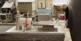 Shaker table system
The shaker table at the UGCL consists of a conventional voice-coil electromagnetic shaker connected to a horizontal steal table and mounted on a granite table for stabilization and isolation purposes. The experiment allows small flexible systems to be attached to the shaker table and be subjected to external vibration disturbances generated by the table to demonstrate resonance modes of a flexible structure. The experiment has several accelerometers that can be used to monitor acceleration of the shaker table and the flexible structure at different locations. Data logging is done via a National Instruments card and special purpose labview Virtual Interfaces (VI's) and can also be used to implement active control schemes to study vibration suppression in a structure. Check out the movies of the controlled flexible tensegrity structure on the shaker table in the download section.
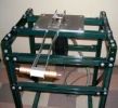 Flexible beam experiment
The flexible beam experiment at the UGCL consists of a heavy-duty metal mounting frame that houses a 3 Horsepower 3 phase induction motor with optical encoder for testing the high speed position control of a flexible load mounted to the motor. The motor has a universal mounting joint on which several flexible arm designs can be mounted and tested for their vibration characteristics. The vibrations in the beam can be observed in the optical encoder mounted on the motor axis, but more accurate measurements of the arm vibrations are obtained by means of an optical encoder or accelerometer mounted at the tip of the arm. The dynamics of the beam is inherently an infinite dimensional dynamical system for which approximations for linear control purposes design must be found. Data acquisition and implementation of feedback controllers is done via National Instrument hardware and Labview. Check out the movies of a controlled flexible beam in the download section.